Introduction.
Splines is a visual vector curve generator in Eurorack format, with a wide frequency range and a built in quantizer, cv scope and cv processing capability.
It can be used in ways similar to a wavetable VCO, LFO, step sequencer or envelope generator.
Onboard quantizer scales, backups and firmware updates are managed as you would use an external USB drive.
It’s a small, shallow, multifaceted addition to any setup, and for touring rigs it can fill many roles in exchange for little space and weight.
Peter Kirn of cdm.link has written a great article about it here: cdm.link/thorn-audio-splines-review
In depth.
In the technical sense "splines" are most commonly used in 3d modelling, animation and vector graphics. It's essentially just a way of creating a curved path from one point to another.
In this module, you have up to sixteen user configurable points or nodes which function much like a step sequencer, where the X axis represents time and the Y axis represents voltage.
When the phase(time) reaches the X position of a node, the 1v/oct output changes to the Y position value of that node.
Each of the sixteen nodes also has a configurable trigger setting, determining if the gate output goes high when the phase crosses the X position of the node.
The nodes are connected by a spline and the shape of this spline is determined by three parameters; Tension, Continuity and Bias. The spline output gives you a voltage following this curve.
Tension changes how extreme the curve between the nodes is.
Continuity sets the angle of the spline at the node.
Bias shifts the Tension to the left or the right of the node.
You can adjust what part of the full spline will be output by changing the Zoom and Scroll parameters.
The curve loops at the end, so when zoomed all the way out, the last node connects to the first.
The speed at which the phase progresses through the nodes can either be set using the "frequency" parameter fluidly, or quantized to fixed frequencies listed in .scl files in the "scales" directory on the module. The cycle frequencies range from 16 minutes per phase to 20kHz, so very slow LFO rates all the way up to the limits of hearing.
The output amplitude can be changed using the level parameter and CV input. This allows the module to be used without a dedicated VCA.
When the spline shape goes higher or lower than the +-5v limits, a few different clipping options are provided, such as wavefolding or soft clipping. Since all parameters can be overdriven substantially, this makes for some interesting effects.
The sync input is also configurable, letting you manage timing like you would a tap tempo lfo, an envelope generator or a step sequencer for instance.
For working with control voltages, a basic rolling oscilloscope is available for each of the six CV inputs, including scaling and offset settings so you can adapt the control voltage signal visually, directly in the module.
Developer resources such as drivers, templates, pin configs and best practices are also provided, in case you would like to use the module as a development platform for your own ESP-32 based DSP projects.
The firmware and quantizer scales can be updated easily by drag and drop via the front accessible USB C port.
Inputs/outputs.
Output res.: 1-16 bits Output sample rate: 192kHz Output voltage range: +-5v CV input res.: 12 bits CV input sample rate: 1kHz CV voltage range: +-5v Trigger duration: 7ms Input trigger: 0-5v
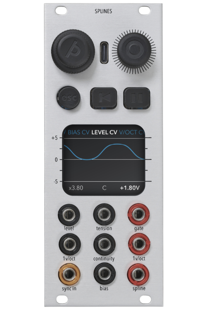
Power.
+12v: 50mA/170mA -12v: 50mA 5v: 170mA/0mA(5v source switchable)
Dimensions.
Depth: 31mm Width: 10hp Height: 3u
Getting started.
Before connecting the module to your power supply bus, please consider if your 5v rail has enough current left over, or if you should rather supply the module from the 12v rail. On the top left of the back of the module, there is a small switch to change the 5v source. By default, the switch is in the external 5v supply position(it gets 5v directly from your power supply). By setting it to internal 5v supply, the onboard LDO will create 5v from your 12v rail, which often has more current capability.
The module comes with nylon screws to protect the front panel. You can replace these with your preferred screws of course, but I recommend using these until you are sure you no longer care if the front panel gets scratched, as this may influence return/resale value. The nylon screws provide more than enough force to hold the module in place.
The Doepfer introduction to modular synthesizers is a great place to start if you are not already a veteran user.
Introduction to modular synthesizers by Doepfer
Doepfer example patches
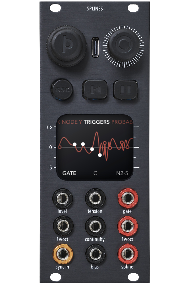
Knobs.
Turning the left knob lets you select the parameter you wish to edit, much like how a rotary switch works.
This knob can be used without ever affecting the output.
Pushing the left knob toggles between Spline view, Settings view and the CV scope. In situations where you need to confirm something, the left knob button serves as "cancel".
Turning the right knob lets you change the value of the selected parameter.
This knob generally affects the output.
Pushing the right knob changes the size of the value steps. The right knob button is also used for toggling values in list contexts and confirming choices.
Step size is indicated in the center of the footer by "C, F or S" for Coarse, Fine or Snap. Where Coarse means larger increments, Fine is small increments and better suited for live modulation of parameters, and Snap jumps to round values. Snap is ideal for accurately setting scroll values for timing, as it snaps the nodes to the 0 phase marker.
Pushing both knobs restarts the module. Release the left one first and keep holding the right knob down to boot in USB mass storage mode, where you can manage files and update the firmware.
(Releasing the right knob button first makes the module enter DFU mode, which is only useful for developers. Push and release the knob buttons in the opposite order to boot normally; left first, right second)
Buttons.
Left button(esc) cancels the current action and escapes to default view.
Center button(reset icon) resets the time/phase to 0.
Within the nodes editing context, this button selects the previous node and holding this button while turning the right knob selects every second neighboring nodes as well. The selection wraps around the visible nodes.
Right button(pause icon) pauses the progression of time.
Within the nodes editing context, this button selects the next node and holding this button while turning the right knob selects the neighboring nodes as well. The selection wraps around the visible nodes.
USB port.
To enter USB mass storage mode to change scales or perform a firmware update:
- Connect USB C data cable to the USB port between the knobs.
- Push and hold both knobs down.
- Release the left knob.
- Keep holding the right knob down until the on-screen countdown is complete.
- The module is now in USB mass storage mode, you can release the right knob.
- Device should appear on your computer as "SPLINES".
Releasing the right knob first makes the module enter DFU mode, which is only useful for developers. Push and release the knobs in the opposite order to boot normally; left first, right second
Firmware update
Drag and drop the firmware file(UF2 file type) into the folder named "firmware". Then reboot the device normally. The firmware file will be detected and installed automatically. After the firmware file has been processed it will be deleted from the folder.
See the downloads section for current firmware versions.
Change scales
Drag and drop scala files(.scl) into the folder named "scales". Then reboot the device normally. The new scales will be parsed and available in the Scales page. There is limited space on this partition, so it can't hold hundreds of scales and presets. A maximum of 30-40 .scl files is recommended.
Backups
Copy the folders in the root directory of the device to your computer for safe keeping or sharing with others.
Reprogramming
You can flash the device directly over USB as you would any microcontroller board. If necessary, push both buttons and release the right one first to enter DFU mode.
Look here for development resources to get started making your own firmware.
Inputs.
Incoming CV is summed with the module settings, so for instance if your level setting is 1.0, you would need to give the module negative voltage to make it silent.
The sync input jack detects the rising edge of square waves and has a few different behaviours you can turn on or off in the sync settings.
Level ranges from 0(no output) to 11 x gain. A setting of 1.0 is normal output with no overdrive applied. For VCA style behaviour, set the level to 0.0 and provide a positive envelope signal at the Level CV input.
1v/oct takes +-5v inputs which allows you to control the frequency output five octaves up or five octaves down from the set frequency.
Tension, Continuity and Bias inputs have possible values of -10.0 to +10.0, represented by -5v to +5v CV inputs.
Outputs.
Gate
The trigger and gate settings for the nodes determine if a signal is output on the gate jack.
When the frequency of the phase cycles is so fast that no meaningful triggers and gates can be created, above 30Hz, this output switches to a 50% duty cycle square wave, for syncing other oscillators for instance.
1v/oct
This output can be configured. It can output either just the 1v/oct input signal, only the nodes Y position value, or both summed. Refer to the Settings section for details.
Spline
The spline output always gives out the Y value of the spline at the current phase position.
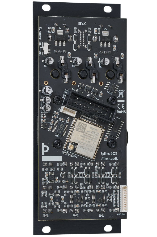
Spline view(default)
The top row holds the available output parameters.
The center area shows the part of the nodes and the spline which is output.
The bottom left shows the set value in white for the current parameter, the bottom right shows the end value in grey including CV and quantizer applied.
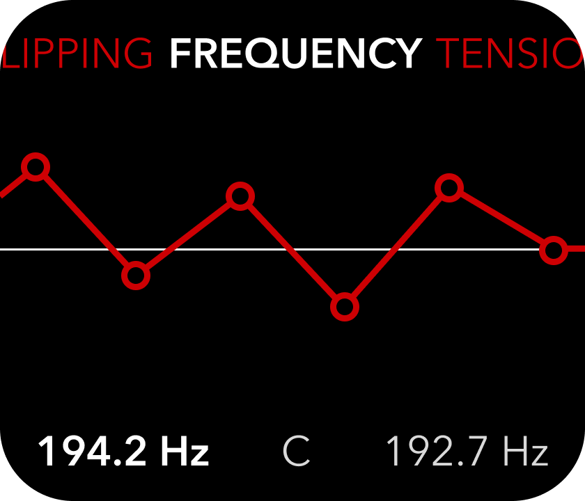
Frequency
rotate the right knob to change the speed at which the waveform is output. The range is between 0.001Hz (approx. 16.6 minutes) and 20kHz. If the quantizer is enabled, the frequency will change in steps, not fluidly. The steps are defined in the scale files that can be changed on your computer via USB.
Below 5Hz, the 0v line will show the progression of the phase, above this rate the line moves too fast and thus becomes solid.
Tension
changing the Tension value alters the amount of curvature between the nodes and affects how much impact Continuity and Bias settings have on the shape.
Continuity
this impacts the angle that the spline enters and exits the nodes. A higher Tension value dictates how much influence this parameter has.
Bias
changes the balance of the Tension between the left and right side of the node. Also has less impact when Tension is closer to 0.0
Level
basically the gain setting. 1.0 is normal output levels, 11.0 is heavily overdriven(11x) while 0.5 is half the amplitude. Set Level to 0.0 to use the Level CV input as a VCA approximation.
Zoom
changes the amount of the spline that is output. What you see on the screen is what is output at the Spline output jack.
Scroll
changes the segment of the spline that is output. Affects timing of gate/trigger outputs.
Node X position
The nodes each have three editable properties; X position(time), Y position(voltage) and trigger/gate setting.
The X position determines when in time the change in voltage will occur, this parameter allows you to offset the node up to the X position of the next or previous node.
Node Y position
The Y position determines how high the voltage should be when the node is reached.
Node Triggers
The trigger setting determines if a trigger or gate signal is output when the node is reached. The options are: off(no signal is output on the gate output jack), trigger(a 7ms pulse is output) and gate(the gate output goes high until the next node is reached).
Trigger probability
You can lower the probability of a trigger/gate being sent out by changing these percentages. It can be easy to forget that you changed these, so the screen will indicate that a trigger output was skipped by briefly blinking the node grey.
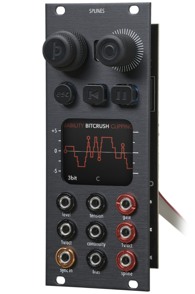
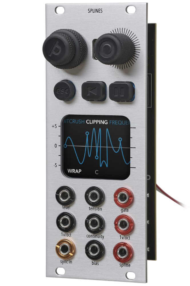
Clipping
Change how the module handles out of bounds waveforms(higher than +5v and lower than -5v). The options are:
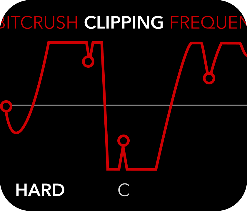
Hard
waveform values higher or lower than +-5v are simply limited to +-5v, creating flat peaks.
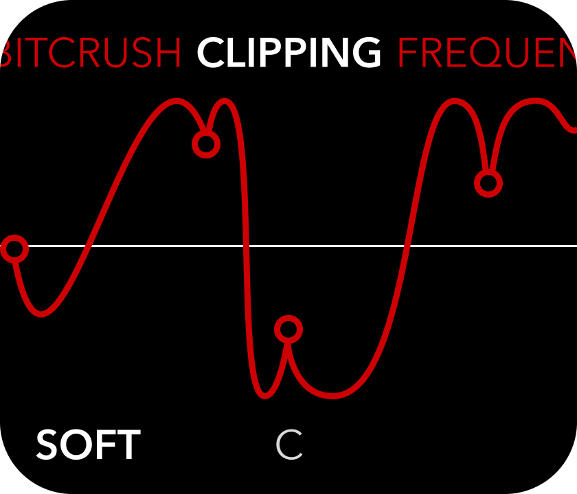
Soft
emulates diode clipping, rounding the peaks as they get near the +-5v limits, making less harsh and abrupt waveforms.
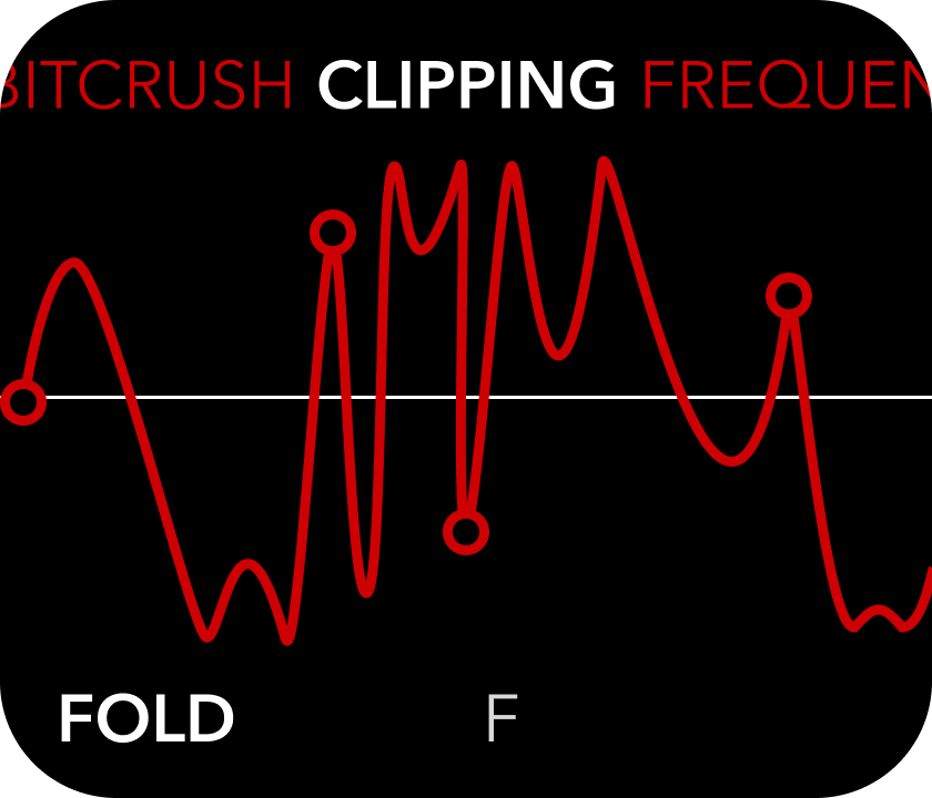
Fold
inverts the direction of the peak as it crosses the +-5v threshold, turning it inwards again. The peaks can be folded many times over for interesting sounding results.
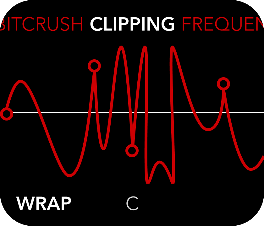
Wrap
overflows the peaks to the opposite side of the range, causing vertical cliffs and very harsh waveforms.
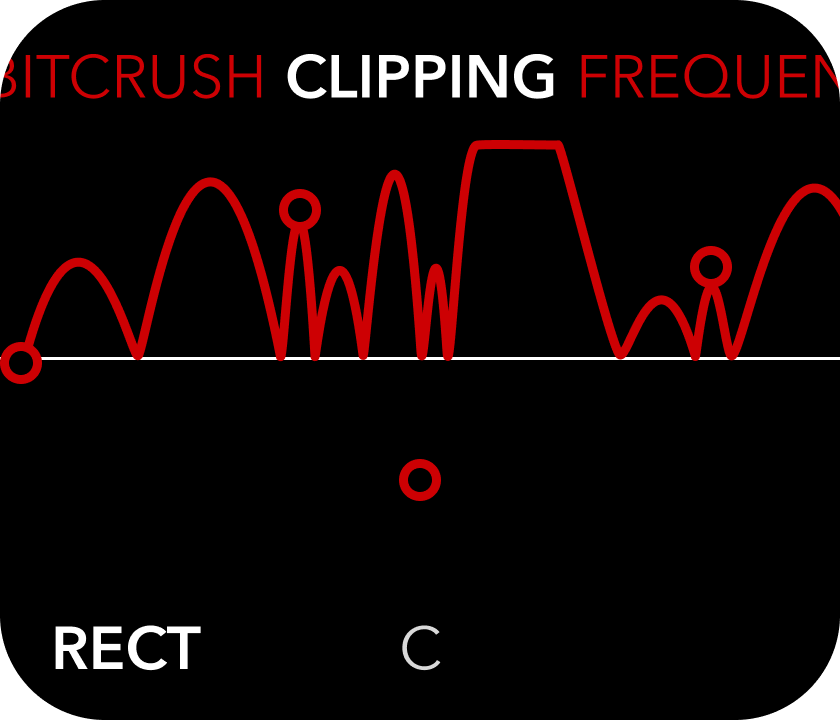
Rectify
Force all of the waveform to be in the positive voltage range, inverting negative segments. Useful for some modulation and envelope purposes.
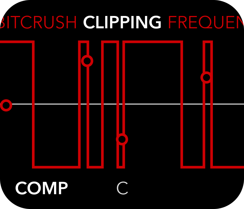
Comparator
Similar to bit resolution 1, turns the waveform into square waves with varying pulse width depending on the spline shape.
Bitcrush
optionally reduce the bit resolution of the output signal from 16 bits(default) down to 1 bit(square waves).
(Push left knob to change view)
Settings view
Change global settings, such as UI color and display orientation, change quantizer scale or save/load global presets.
Settings: Move right knob to select an object in the list, push right knob to toggle on/off.
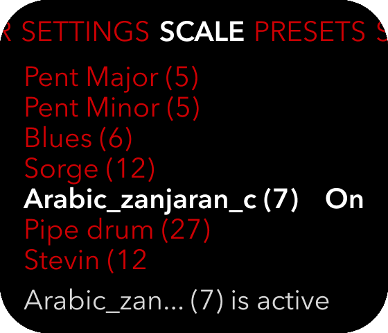
Scales
The frequency of the phase progression and the static voltage output can be quantized to fixed values according to .scl files loaded onto the device using the USB port between the knobs.
To enable a specific scale, push the left knob once to enter the settings view and rotate it until you reach the SCALES sub page. Then use the right knob to select a scale from the list. The list of scales is updated on boot according to the content of the /scales directory.
If a .scl file cannot be parsed, it will simply not appear in the list. Please ensure that the formatting of the .scl files follows common practices.
There are many existing scales to try out here:
Or you can create your own using an online scale editor
The quantizer “locks” to the nearest value in the scale, and requires the incoming voltage to change a bit before it locks onto another value. This is to prevent “quantizer chatter” where minor fluctuations in voltage causes the frequency to oscillate between two values in the scale. The concept itself is called hysteresis, but it just means there is a dead zone between the notes in the scale where small changes do not affect the output.
You can change what the quantizer applies to in the settings view.
Sync
The sync input jack detects the rising edge of square waves and has a few different behaviours you can turn on or off:
Looping
If the phase should pause or not after playthrough. If off, a sync input pulse unpauses the phase.
Reset phase
when a trigger or gate is detected on the sync input, the phase progression is reset to 0(time starts over).
Tap Tempo
when a trigger or gate is detected on the sync input, or the (center) reset button is tapped, the time passed since the last incoming sync signal is calculated and the frequency of the phase is matched to this interval.
Enabling tap tempo also enables clock multiplication and division in place of the frequency setting.
Step
1v/oct output jumps to the next node X position every time the phase loops, much like a step sequencer.
Ext. Clock
Detach the step sequencer from the main phase and clock it externally using the sync input. The phase progression of the spline output is then running at a different rate than the 1v/oct output, which only changes when a pulse is detected on the sync input.
Sample & Hold
Samples the 1v/oct input at the time of an incoming sync signal. The sampled value is then optionally quantized and output to the 1v/oct output jack.
Presets
Save, load, update or rename presets.
By pushing the right knob when Create preset is highlighted, you can save the current settings for later recollection.
When you push the right knob the screen will change to a naming interface where left knob changes the cursor position and the right knob changes the letter. Push the right knob again to save, push the left knob to cancel.
The saved name will always appear in the UI color selected in the System settings menu.
Selecting an existing preset and pushing the right knob will open the options for that preset, which include load, rename, update and delete. If you load the preset, your current settings will then be overwritten and will not be retrievable unless you saved them first. If you have made changes and wish to update the preset, you can choose update and your current settings will be written to this preset. Rename opens the naming interface and saves the same preset with a new name. Deleting the preset will require additional confirmation.
Loading the factory settings purges the persistent memory and zeros the settings to default values. This might be useful in case of corrupted memory or other problems with the device.
The preset file contains all the current settings and can be copied to other Splines modules or backed up to your computer.
UI color
Select the primary color for the UI.
The active color is also used to differentiate the list of presets when they are saved.
Settings
These are additional settings that don't gracefully fit into the main UI layout. I have decided to let users turn them on or off independently of one another, even though some of the settings may override/interfere with others, but since they still produce interesting results, I leave it up to you to experiment.
Quantize frequency
Whether or not the quantizer applies to the phase frequency.
Quantize voltages
Whether or not the quantizer applies to output voltages.
Forward 1v/oct
When active, the 1v/oct output will only output the incoming signal at 1v/oct input, optionally quantized, so that you can use the quantizer independently of the spline output.
Transpose nodes
Turn on or off if the node Y positions are affected by 1v/oct input signals.
TCB expander
Turn on or off the expansion module. This module is not yet in production, but will add two more CV inputs for scroll and zoom, and potentiometers for the most important parameters, for more tactile control. Leaving it off ensures that the extra CV inputs do not accidentally affect the scroll and zoom values.
Time unit
Change from Hz to milliseconds.
Bright display
Increased display brightness for sunny days.
Flip display
This setting flips the display upside down and inverts the left/right function of the buttons.
Endless menus
If menus should loop at the ends or not.
Firmware
Displays the firmware version installed, so you can see if you need an update or not, or for debugging purposes.
CV Scope.
Monitor incoming CV and change scale and offset for all the CV inputs.
Navigate between CV inputs using the left knob. Use the reset button to select Gain and the pause button to select Offset.
All CV inputs are set up for -5v to +5v input signals.
If the input voltages exceed the range, the signal will be clipped by protective diodes before it reaches the ADC.
You can scale and offset the incoming CV for each input.
How do I...
- use Splines as a VCO.
To use the module as a VCO, first increase the frequency setting to something above 30Hz and patch it into your output mixer.
I'd recommend checking that Looping is on in your Sync settings and optionally check that "Quantize frequency" is on in Settings.
Take a control voltage source and patch it into the 1v/oct input. You should now get musical notes out of the Spline output. Play around with Clipping modes and overdrive for grungier sounds and effects.
The Gate output now works as a square wave oscillator at the same base frequency as the Spline output.
The 1v/oct output is outputting the Y positions of the nodes. Alternatively you can turn on "Forward 1v/oct" and use this output as a quantizer independently.
You can also use the Level input directly with an envelope signal in place of a VCA. Set Level to 0.0 and patch in a positive envelope signal to control the output volume.
- use it as a step sequencer.
To use the module as a simple step sequencer, change the Sync mode to "step" and patch in a gate or trigger source to the Sync input. The phase progression will be paused and it will jump right from one node to the next every time a pulse is detected.
You can continually transpose the entire sequence without affecting the frequency by going to settings and enabling "Transpose Nodes", then patching a transposition signal to the 1v/oct input.
- externally clock the steps.
Go to Settings and activate both Ext. Clock and Step. The module will then use the sync input pulses to progress the step sequencer instead of the internal phase reset. The spline output then runs on the internal clock separately.
- use it as an LFO.
The normal LFO mode is simply the same as the VCO mode but at a slower phase frequency setting.
You can also change the Sync setting to "tap tempo" which will make the phase frequency match the time interval between incoming pulses on the Gate input and enables the clock multiplier/divider feature. You can also tap the center button(reset) to tap out an interval.
- externally sync the LFO.
If you enable Tap Tempo, the frequency will be automatically adjusted to match the period of the incoming pulses on the sync input or the taps on the center button(reset). You can then use the right knob to set clock division and multiplication.
- use it as an envelope generator.
By turning off Looping in the Sync view, you can use the module as a complex envelope generator. The phase will now pause at the end and will hold for a sync input pulse. Turn on Reset phase in the Sync view to allow for mid-phase retriggers.
You can set the timing units to milliseconds in the Settings page if you prefer that.
- select and edit multiple nodes.
Hold down the pause button(rightmost button) while turning the right knob. This will select neighboring nodes as well. Release the button to adjust the value for all the nodes at the same time. Their values will be adjusted from their individual starting points, so their relative difference in settings will remain. Using the reset button(middle button) instead will select every other neighboring node.
- alter the quantizer scales.
You can change the scales by connecting a USB C data cable to the module and holding the right knob down on boot. The module will then appear on your computer as "SPLINES". Inside there are three directories, one of which is called "scales" and contains the quantizer scales. The church modes are part of the firmware, but the other scales in this folder can be deleted, edited or replaced. Just ensure that the formatting of the files is consistent with the .scl file format conventions.
- make a backup.
Connect to the module using a USB C data cable and restart while holding the right knob down. Copy all of the content from the SPLINES drive to your computer for safekeeping.
- move your presets to another unit.
Connect to the module using a USB C data cable and restart while holding the right knob down. Copy the presets and scales directories from the SPLINES drive to your computer, repeat process in reverse with another unit. Do NOT copy the calibration.txt file to another device, as this file is unique to each device. If you do this by accident, simply delete the calibration.txt file and it will be recreated from internally stored factory calibration data.
- update the firmware.
Connect to the module using a USB C data cable and restart while holding the right knob down. Download the new firmware file from this site, and place it in the firmware directory on the SPLINES drive. Then eject and restart the module and you will be prompted if you want to update the firmware. Push the right knob to proceed.
- reset to default values.
Go to the presets list and load the factory settings in grey at the bottom of the list. This will zero all of the persistent memory settings and load default values.
- calibrate the inputs/outputs.
The module comes with a step by step calibration process.
You first need a precise multimeter. Then go to the CV Scope view(any page), and push both the center (Reset) and right (Pause) buttons at the same time. This will start the calibration process. Instructions will appear on screen, but the process is as follows;
- Calibrate the spline output using your multimeter and the right knob
- Push the rightmost button(pause) to confirm the calibration
- Patch the spline output into the level cv input
- Push the rightmost button(pause) to calibrate the input
- Repeat for each other input
- As the last step, calibrate the 1v/oct output using your multimeter as you did the spline output, then push the pause button again to finish the calibration
The calibration data is stored in two places, on the persistent memory module and in flash memory on the USB partition as a calibration.txt file. You can edit this file manually over USB, and it will overrule the stored calibration. If you delete this file, it will be recreated using the internally stored values. This is a backup feature to prevent accidental loss of the calibration.
More conveniently, you can also adjust calibration using the CV scope's per-channel gain and offset settings, but these settings will be reset if a preset is loaded!
FAQ.
Some commonly asked questions and answers.
Can I make my own firmware for it?
Yes please! The resources you need to get going are hosted in this git repo: splines_templates
How fast is the trigger response from sync to output?
There is roughly 2ms delay from sync input to trigger output, since the module is prioritising DAC output.
At frequencies above 6kHz there are sometimes tones in the output that are not part of the waveform.
This is called Nyquist Aliasing, and is related to the harmonic overtones created by near instant changes in voltage. The DAC and Opamps are capable of outputting large voltage changes in the nanosecond range and these changes create high frequency overtones that fold back into the audio range, producing harmonics. This is avoidable by using the output parameters to round the peaks manually or activating soft clipping.
Send questions and feedback to support@thorn.audio and I will answer them as soon as I can.
Downloads.
The included presets are as follows:
- Blank Pattern.spl: A blank start with neutral settings.
- Envelope Bounce.spl: Using rectify clipping to create a bouncing voltage that plays once.
- Envelope.spl: Approximating a normal envelope shape using node positions. Looping turned off.
- LFO Tap Tempo.spl: Tap tempo on, frequency 1Hz
- LFO.spl: Tap tempo off, frequency 1Hz
- Quantizer SH.spl: Samples the 1v/oct input on sync pulses, quantizes it and outputs it on 1v/oct out.
- Step Seq Extern.spl: Externally clocked step sequencer mode, with independent spline output
- Step Seq Intern.spl: Internally clocked step sequencer mode
- VCO Fold.spl: More complex VCO approximation with wavefolding active
- VCO Saw.spl: Classic saw waveform output
- VCO Sine 4 Bit.spl: Bitcrushed sine waveform output
- VCO Sine.spl: Classic sine waveform output
- VCO Square.spl: Classic square waveform output
- VCO Triangle.spl: Classic triangle waveform output
The preset files are human readable, so you can open them in textedit over USB and have a look at the exact settings and edit them as you want.
The "church modes" are part of the firmware, but all the other scales are .scl files on the USB drive partition which can be deleted or edited. I have selected some scales from the scala library that I found interesting, but there isn't much more thought put into the example scales included with the device.
The scales in the .zip file are as follows, with their included comment:
- Arabic zanjaran on c.scl: Arabic Zanjaran with perde rast on C by Dr. Oz.
- Blues.scl: 6-note blues scale with flat 5th
- Bohlen pierce.scl: See Bohlen, H. 13-Tonstufen in der Duodezime, Acustica 39: 76-86 (1978)
- Hindustani.scl: North Indian Gamut, modern Hindustani gamut out of 22 or more shrutis
- Iranian pentachord 7-limit.scl: Iranian pentachord 42:45:48:56:63
- Lebanon.scl: Lebanese scale. Dastgah Shur
- Stellarhex.scl: Mandala/stelhex/cube(2) plus 7/6 and 7/5; convex in marvel tempering
There are many more existing scales to try out here:
Or you can create your own using an online scale editor
Developer resources.
Since the format and architecture of the module lends itself to many other potential uses, I have created some developer resources that will help you get started with making your own firmware for it.
The hardware specs are as follows;
- 1.83" 284 x 240 full color ST7789P LCD over SPI
- ESP32-S3 WROOM 1U N8R8 with wifi and low power bluetooth
- PCM5102 32-bit 384kHz stereo DAC over I2S
- MCP3208 8-channel 12-bit ADC up to 100 ksps over SPI
- FM25V10 FE-RAM 1 mbit persistent memory module over SPI
- Breakout connectors for all ADC channels and i2c are provided for expansion modules as well.
Templates, drivers, pin configurations and basic instructions can be found in this github repository: splines_templates
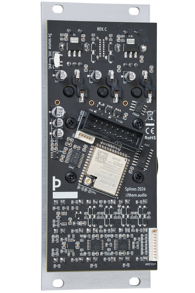
Expansion ports.
The module has two expansion connectors on the back. One for i2c and one for 6 ADC channels.
There should be plenty of power available for most purposes.
The i2c connector pinout is, from left to right:
- 3.3v
- GND
- Interrupt
- SCL
- SDA
The ADC Exp. connector pinout is, from top to bottom:
- Scroll CV(expander only)
- Zoom CV(expander only)
- Level CV
- Bias CV
- Continuity CV
- Tension CV
- GND
- -12v
- +12v
- +5v
Support and repairs.
The module is easy to disassemble without special tools and replacement parts are freely available.
- 5v power source switch: Alps Alpine SSSS810701
- Left encoder(detented): Bourns PEC11R-4220F-S0024
- Right encoder: Bourns PEC11R-4020F-S0024
- Mechanical keyswitches: Kailh Choc V2 low profile blue
- Hot-swap sockets for keyswitches: Kailh CPG135001S30
- Display: Waveshare 1.83" LCD module
- Display mounting screws: M2.5 8mm
- Jacks: Thonkiconn mono
- Jack nuts: Bananuts by Befaco
- Signal diodes: NRVB130T1G
- Polarity protection diodes: 1N5817W
- Input opamps: TL074CPWR
- Gate output opamp: NE5532MM/TR
- Output opamp: OPA1678IDGKR
- Knobs and buttons: 3d printed, models can be found here
Get in touch with support@thorn.audio for more detailed information when necessary.
Videos/reviews.
Product photos.
Press articles
Retail outlets(more coming):
Credits.
- UX concept, UI design, illustrations, testing and final assembly by Joni Caparas
- Concept, product and hardware design by Hallvard Kristiansen
- Manual written, designed and built by Hallvard Kristiansen
- Firmware written wrong a lot by an LLM and tediously corrected by Hallvard Kristiansen
- PCB manufacture and assembly by PCBGOGO
- Front panels manufactured by Grawart
- Bananuts by Befaco
Special thanks to:
Alex4 for believing in the concept and preordering enough units so I could finish the project. Joni Caparas for having patience and bringing enthusiasm and experience to the process. Andreas Schneider for the trust and for keeping me fed for four years. Sylwester Sosnowski for years of hardware discussions, advice and support.
Everyone who took part in beta testing
- Peter Kirn
- Sylwester Sosnowski
- Henning Schönvogel
- Jamaica Suk
- Ben Lukas Boysen
- Lisa Morgenstern
- Astrid Bin
- Mathieu Pé
- René Margraff
- Barry Tracey
- All my colleagues at Schneidersladen
My family who bought me a 3d printer for the project
- Astri Normann
- Aslak Kristiansen
- Sigurd Kristiansen